 |
| Email Home Page |
|
| Email Home Page |
|
|
This modifier allows you to generate a series of components. They are generally envenly spaced and in the simplest applications can be produced in a straight line or in a circle with just a few simple steps. It's accessed like other modifiers WRENCH icon in the properties panel >> ADD MODIFIER >> select ARRAY. Although the following is mostly useless, it shows what can be done in less than a minute.
For this next example, you'll use the following settings. The red arrow means that you don't want it ticked. The green are the items that you'll want ticked or will enter. The yellow are buttons that you'll click or something you need to take note of.
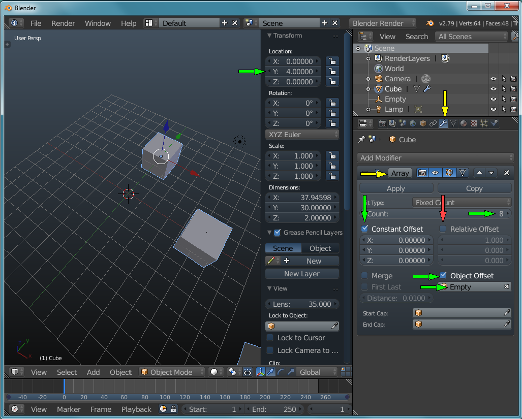
The following shows what an EMPTY looks like when selected. When not selected, the axes (which are 1 unit in length from its origin) are black and are relatively hard to see. Previously, it was stated that you need to select the object that you intend to array before selecting the MODIFIER's wrench icon. If the EMPTY is selected, the wrench icon won't be available.
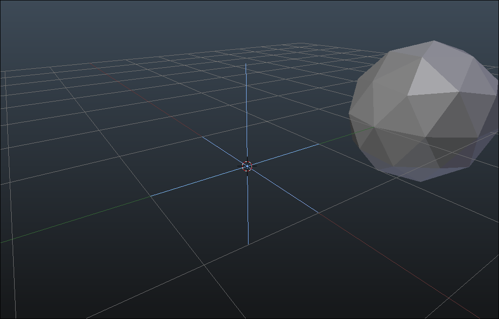
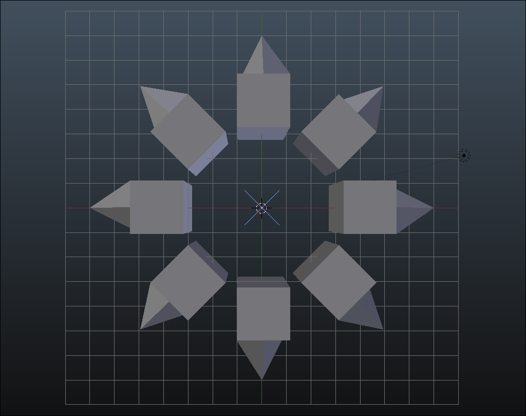
The image above shows the results when the origin is relocated to the point of reference. You can see the blue dot that indicates the origin of the selected object at the center of the grid. The image below shows how the objects will rotate when the origin is not relocated to the point of the reference (the EMPTY). The origin can be seen in the body of the 'cube'.
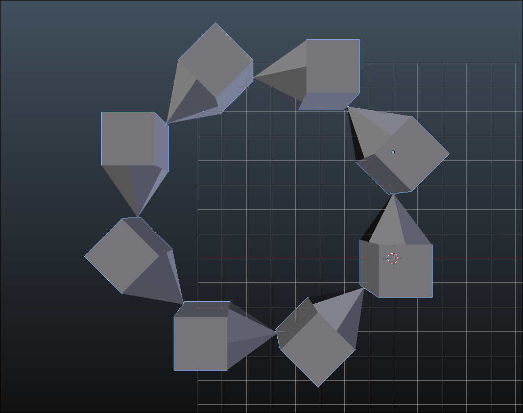
offset origin if you don't want the object to rotate when the array is rotated.
The original object will rotate out of its position by the degrees in the Y field in it's properties menu. The second iteration will be in its original location.
The group will pass from the Y axis position through the Y axis position for the reference (often an 'EMPTY'). To get the array to stay on the plane, put both the object that's to be arrayed on the same Y coordinates as the reference.
Make mods in the edit mode. modifications to scaling, dimensions or rotation will result in unexpected changes.
If you scale an object like a cylinder or cube down on the y axis and you use a reference when arraying, you must also set the reference to the same scale to prevent strange things from happening when you rotate the array.
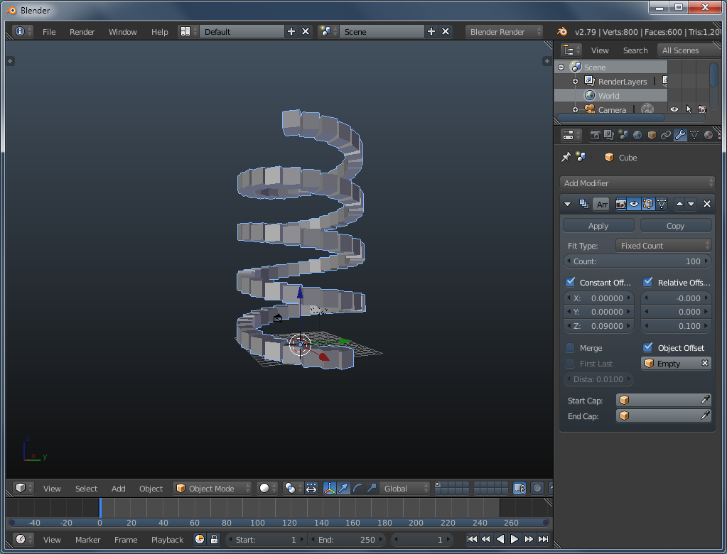
Remember that you can constrain the rotation to one of the three axes. Do that here. Click the R-key, then the Z-key and move the mouse to start the rotation. Click when you get close to closing the circle. You have 8 objects and the circle has 360°. 360/8 is 45. The Y rotation should be near 45° (or -45°). Set the Z rotation to exactly 45°. An alternative method is to rotate the empty by the amount that you wound need to enter into the text field. This will automatically rotate the array without using the R-Z.
Welds
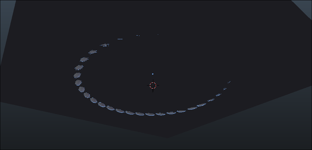
This was my first attempt at simulating a weld. The individual puddles are a torus. They were angled at about 45° to go in the 90° joint created by the two cylinders. The EMPTY was angled so the new torus would be placed on top of the previous one. When the array was done, it was at the angle of the EMPTY (2-3°). Rotate around the correct diameter (determined by offset from empty). Remember that welds are not surface features and need to look like there was penetration.
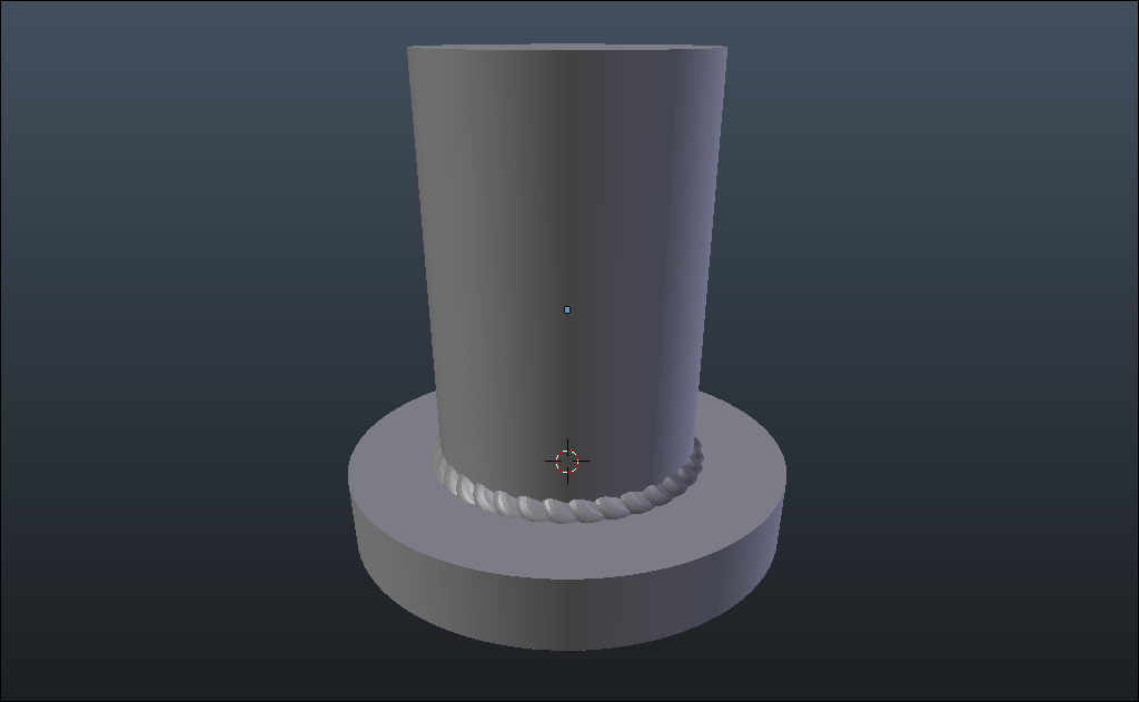
A note on the torus used in the weld. The center hole was too deep to work without modification. The center was raised to just about level with the outer ring. It was jut slightly angled up as well as at the 45° angle mentioned above. Remember, all mods and angle changes need to be done in the EDIT mode, NOT the OBJECT mode.
To get the array of welds back parallel with the grid, I tried to do it by eye but that was not happening. What did work was adding a plane larger than the array. The plane was lowered by 0.1 units to get it below the grid (less distraction). Leveling was done by lowering the array down until it just started to protrude through the plane. Then, by using the input for the angle for the weld array in the N-panel, it was easy to get all of the array protruding the same.