Home > Facilities > Integrating Sphere
 Integrating Sphere
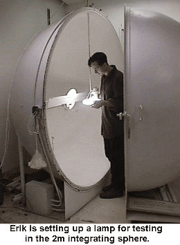
The integrating sphere is used to quickly measure the total light output of a lamp. The lamp being tested is placed in the center of the integrating sphere. At one side of the sphere is a light meter which measures the light output of the lamp. Between the lamp and the light meter there is a baffle to prevent the meter from seeing any direct light from the lamp.
The inside of the sphere (including the baffle) is coated with a very white paint that reflects all wavelengths equally. This allows us to get very accurate measurements. The light from the lamp bounces around the sphere until it reaches the light meter.
It is important that nothing else is in the sphere besides the lamp and the baffle. Anything else placed in the sphere, like a fixture, would absorb some of the light. So if anything besides the lamp and baffle is placed in the sphere, not all of the light reaches the light meter and this results in erroneous meter readings. This means that we can only obtain "bare lamp" readings in the sphere. The integrating sphere cannot measure the light output of the lamp in fixture (which the goniometer can).
The integrating sphere is also different from the gonio-photometer because the sphere only measures the total light output of a lamp and not the direction.
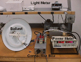
 To
the left is a picture of the equipment we use with the sphere. The
light meter displays the light level being measured inside the sphere.
We use the power meter to make sure we have the proper voltage and also
to check the lamp's power usage. A ballast is necessary to run most
non-incandescent lamps. The ballast cannot be in the sphere because it
would interfere with the light reading. Finally, the connection box is
needed to connect the ballast to the lamp inside the sphere and to the
power supply.
 Gonio-Photometer
The gonio-photometer (or goniometer for short) is able to measure the illuminance from each portion of a lamp or fixture. There are three main components to the goniometer: (1) the rotating table that the fixture or lamp is placed on, (2) the long arm with a mirror on the end that rotates around the fixture and (3) a light sensor that measures the light reflected by the mirror.
The light source (whether it is in a fixture or not) is placed in the middle of the goniometer, sitting on the rotating table. The rotating table can be adjusted up and down to make sure that the light source is in the very center of the goniometer. When the lamp is positioned this way, the mirror at the end of the rotating arm is positioned so that it reflects the light from the light source directly to a light sensor at the opposite end of the room.
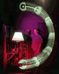
The arm with the mirror rotates from bottom to top around the lamp, stopping every few degrees so the light meter can take a measurement. The time-lapse picture above was taken from almost the same position as the light sensor. The picture shows how the sensor can see the lamp from every angle that the mirror reaches. One rotation from bottom to top of the mirror is called a "sweep."
After the first sweep, the mirror is lowered back to the bottom and then the rotating table rotates a pre-set number of degrees (depending on the symmetry of the light source and how detailed we want our measuremens to be). After the table rotates, the arm with the mirror does another sweep of measurements.
This process is repeated until we obtain a map of the entire lamp. A complete test takes anywhere from ten minutes to two hours, depending on the detail we need (greater detail takes more time).

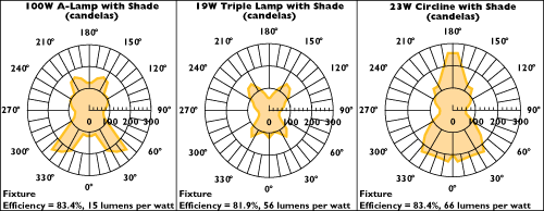
The graphic above demonstrates the sort of output we obtain from our measurment. Each of the three graphs shows only one sweep of the mirror arm. Even though the mirror arm only rotates 180 degrees around the lamp, if the fixture is bi-symmetrical we are able to reflect the results across the 0-180 degree axis and obtain a 360 degree graph of the fixture illuminance.
The longer the radius from the center to the plot line at a certain angle, the greater the intensity at that angle. So to find out the illuminance at 90 degrees for the graph at the left, follow the line from the center of the graph to the 90 degree mark. The plot line intersects the scale at about 80 candela (a unit of measurement for light). This can be done at any angle around the graph.