 |
| Email Home Page |
|
| Email Home Page |
|
|
|
Part 4
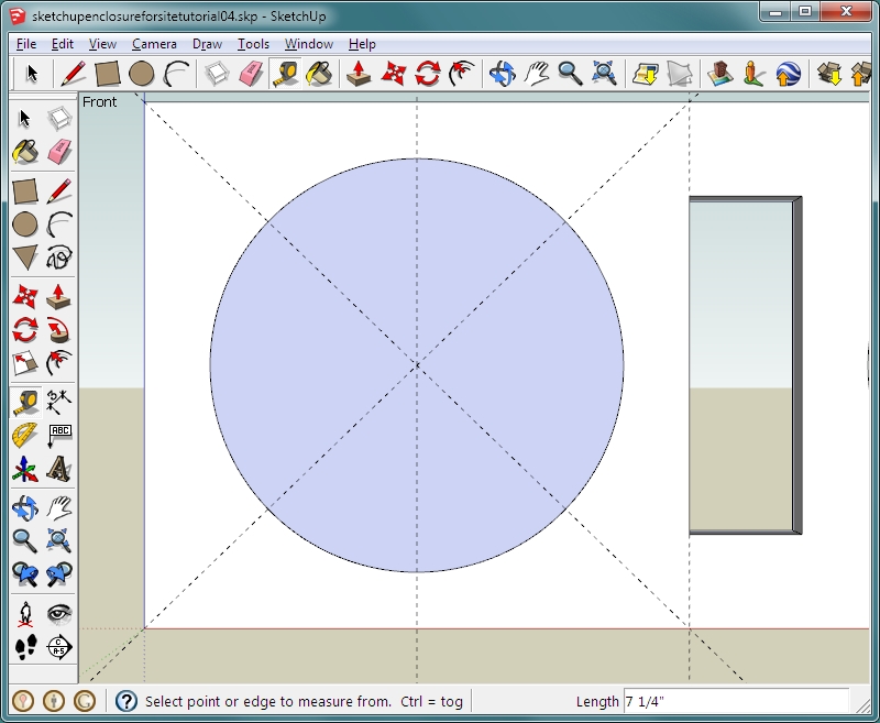
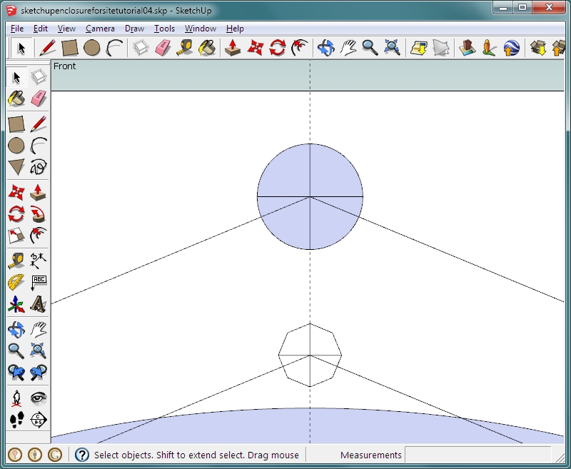
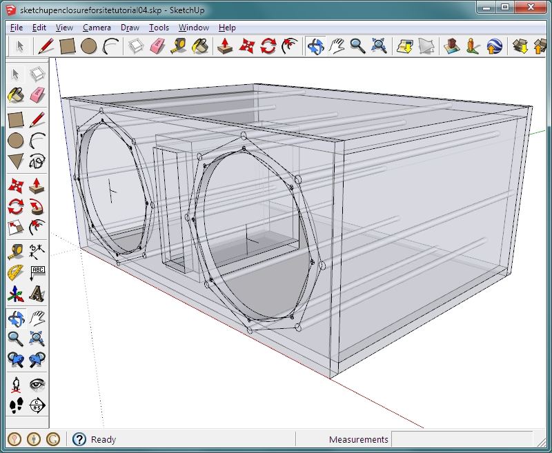
How about a few more tools... Let's say that you want to add some reinforcements for the baffle as well as marking the screw holes. Open the file above and change the camera angle to 'iso'. Hold the control button down and click 'a' (ctrl-a). This will select all parts of the enclosure. Click the SELECT tool. Hold the shift key down and click on the baffle. Now right-click on one of the highlighted panels and choose HIDE from the menu. This should leave only the baffle displayed. Change the camera angle to 'front'. Select the front baffle so that it's highlighted and right-click. Choose EXPLODE from the menu. This will break the group. This will prevent having the group close without you knowing while you're zoomed in. Zoom in on the left front speaker cutout. You should be able to see the front and rear circles that represent the cutout on the front and back of each face (front and back) of the baffle. Click the rear one so that it's highlighted all around and delete it. Change the style (WINDOW >> STYLES) to the DEFAULT style. If you can see guide lines, go to EDIT and click DELETE GUIDES. Using the TAPE MEASURE tool, drag a guide line from the left edge of the baffle to the left opening of the port. Make two more diagonal guide lines and a vertical center line in the circle. You should have something like what you see below. Use the ZOOM EXTENTS tool so that you can see everything on the stage. Use ctrl-a to select all and make it a group.
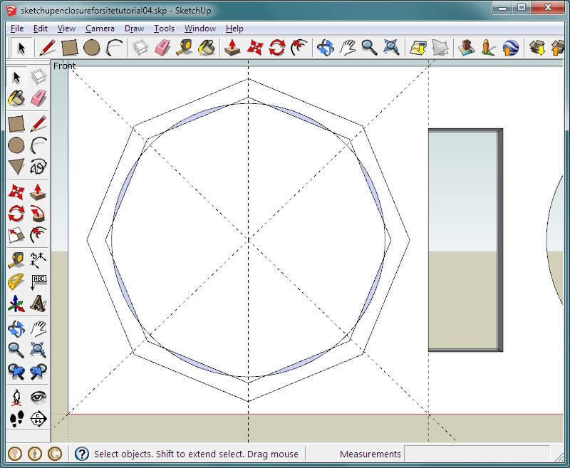
 Let's say that your speaker has 8 mounting holes with holes at the 12, 3, 6 and 9 o'clock positions. With the SELECT tool, click the circle and make it a group. Choose the circle tool and type 8 into the text field before clicking on anything. That will make a circle with 8 segments. Click the center of the diagonal lines, position the cursor so that it snaps to the vertical line and enter 5.75 in the text field. 5.75 was used here but you would use whatever radius corresponded to the radius of the holes in your speaker. Do this again but set the radius to 6.5". You should have something like this...
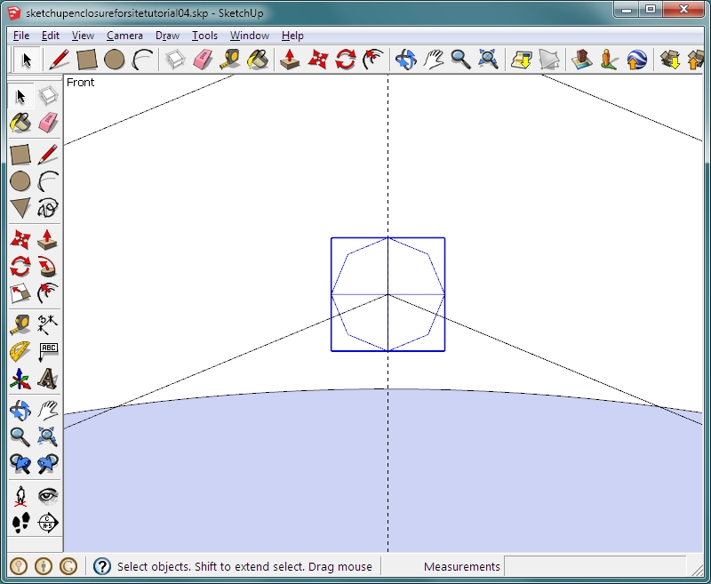
 Click inside each of the newly created octagons to select their fill areas and delete them. Select and make each of the new 8-segment 'circles' a group (one per group). Zoom in to the top of the smaller octagon. Choose the CIRCLE tool again. It should have '8' in the text field. If it does not, enter 8. Start a circle, aligning the cursor with the vertical guide line and enter 0.15 in the text field. Click the LINE tool (pencil) and make two lines top to bottom and left to right in the newly created octagon. Triple-click inside the newly created 0.3" octagon and right-click it. Choose MAKE COMPONENT and name it mounting point.
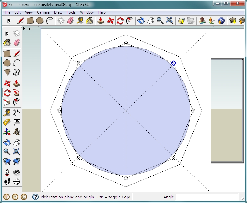
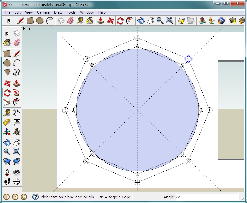
 Zoom out so that you can see the entire left side of the enclosure, including the two large octagons. You now need to place the rest of the mounting points. You could copy and paste these points but there is an easier way. Remember that you copied the end panel of the box by holding the control button down while using the MOVE tool. You can do the same with the ROTATE tool. Use the SELECT tool to highlight the mounting point component (if it's not already highlighted). Select the ROTATE tool and click on the center of the speaker cutout (intersection of diagonal lines). Hold the control button down and click on the highlighted mounting point. Release the control button and type 45 into the text field and hit enter. Immediately type 7x into the text field and hit the enter key. This should have copied and rotated the mounting point 7 more times. They should all be aligned perfectly on the vertices of the octagon.
 The baffles of some enclosures flex a bit too much because so much wood has been cut away (or simply because they're so large). Let's add a few braces for this baffle. We will use the same basic technique used for the mounting points. Zoom in on the top of the larger octagon. This time, the holes will be round but we will start with the same octagon. This time, it will be for a 1/2" dowel so the radius will be 0.25. Choose the CIRCLE tool and again make a 'circle' on the top vertex of the larger octagon. After drawing the initial 1/2" octagon, delete it's center fill. Draw the lines in it like you did before. Now select and delete all of the perimeter segments, leaving only the cross. Select the CIRCLE tool again. Enter 360 in the text field before clicking on the crossed lines that you just drew. After clicking, again enter 0.25. It should look like this:
 Select the 1/2" circle and the two crossed lines and make them a COMPONENT named 'dowel 1'. With the newly created circle highlighted and the ROTATE tool selected, click on the center of the speaker cutout, hold the control button and click the newly created circle. Enter 45 in the text field and then enter 7x like you did previously.
 Now we need to make the cutout again. For some reason, this program seems to have a problem when too many segments are used when drawing a circle. We drew these with 360 segments. I could not select the circle. To get rid of it, I deleted the center fill then I used the select tool to drag a selection box from outside the face to around the circle. It selected only the circle and that allowed me to delete the circle. Drawing another circle (5.5" radius) and pushing it to the back top edge of the board was simple enough.
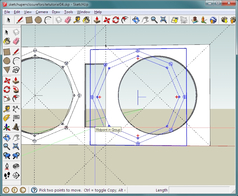
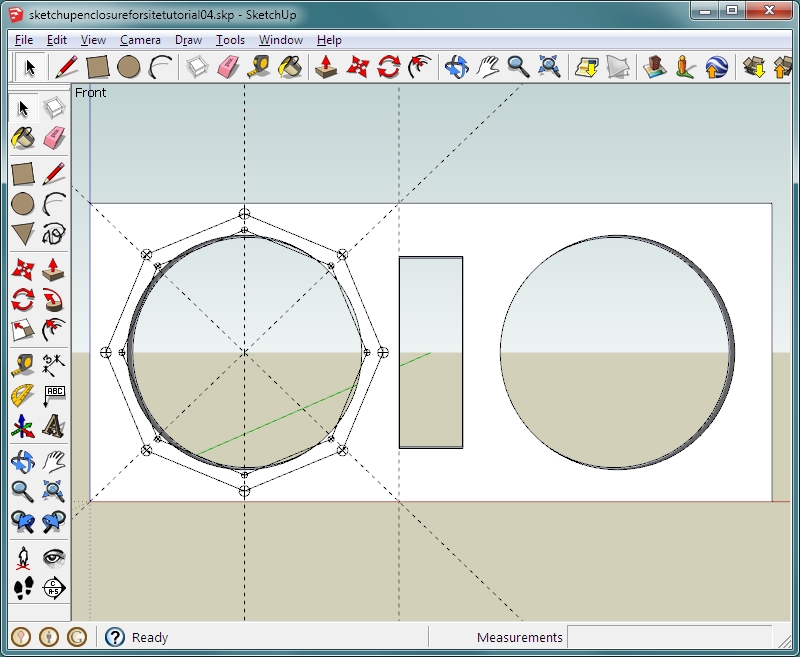 Now, this may seem like a lot of work (but it's really not when you get familiar with the software). We can copy all of this work to the other cutout. Make the guide lines for the right-side cutout like you did for the first cutout. Zoom in so that you can see all of the components that you created on the left side. With the line tool, make a line through the center of the cutout. Make another one from the intersection of the lines out about 1" from the center. Use the escape key to break the line when you go from one line to a new line. We will use these to center the drawing on the other side. It should look like this. Go to EDIT and MAKE COMPONENT. Name the component 'layout marks'. Select the newly created component so that it's highlighted. Use ctrl-c to copy it and ctrl-v to drop it. Use the mouse to drop it where the center cross is on part of the background. Use the SELECT tool to select the component. Use the MOVE tool to grab the crossed lines at their intersection and drop them on the center of the diagonal lines on the right-side cutout.
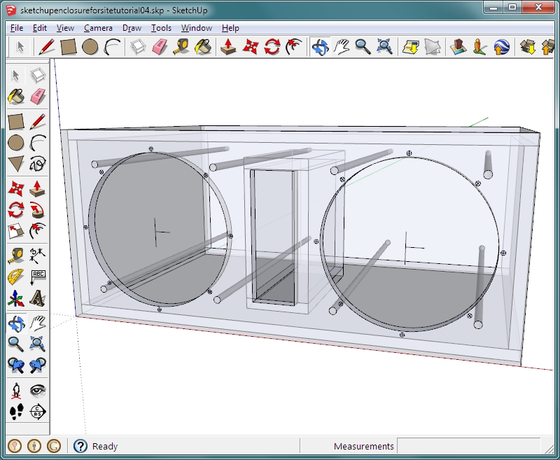
 Now, let's extrude the dowels. select and hide the baffle. Orbit around to the back of what would be the baffle and double-click one of the dowels. That will get you into the layout marks component. Then double-click one of the dowels. Delete the 4 line segments and pull the dowel back 23 " (enter 23 in the text field). That will take it from the front surface of the baffle to the rear surface of the back panel of the enclosure (the ends of dowels will be flush with the outside surfaces of both boards). Double-click outside of the groups and components to exit all of them. UN-HIDE all components, change view to ISO and change style to x-ray. Go to VIEW and de-select GUIDES. If you orbit around to the front, you will see that several of the dowels are going through other objects. Since the problems are the same for both of the layout marks components, you can edit one to remove all of the problem components.
 If you had different objects in the 'layout marks' components causing problems, you could do a couple of things. If you thought that you would re-use the layout marks component, you would highlight it and right-click it. Then you'd select 'make unique' from the menu. That would make a copy of it in the library. You could also highlight it and select EXPLODE. That would break it up and editing its components would not have any effect on the still-intact 'layout marks' component. You would do this to both sides and edit them individually. When editing the components, I also removed the octagons that were used in the layout.
 THIS is the file for the above enclosure. This is the end of part 4 of the Sketchup tutorial. Click HERE to go to part 5 (10e in the directory).
|
|
|
|