 |
| Email Home Page |
|
| Email Home Page |
|
|
|
Note:
Overview:
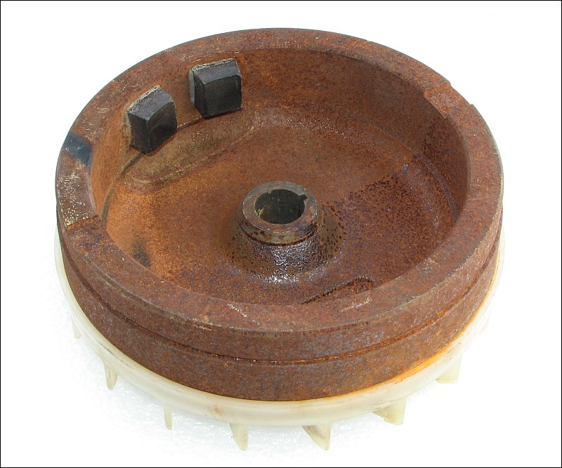
Flywheel: The next image is the back side of the flywheel. As you can see this a massive piece of iron. The two black items are magnets. On some flywheels, the magnets are inside the rim but most magnets are on the outside of the rim.
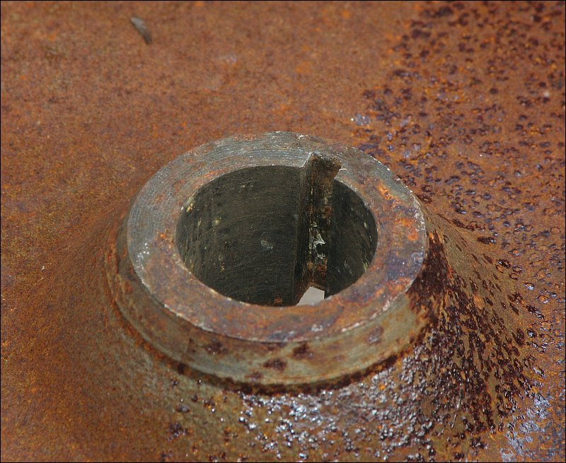
 Below, you can see the center bore in the flywheel. The slot in the bore is the keyway. This slot is kept in alignment with the slot in the crankshaft by a piece of keystock. The flywheel has to be synchronized or 'in time' with the crankshaft because the magnets that help create the high voltage that produces the spark have to pass over the poles of the ignition coil at precisely the right time.
 Below, you can see the area that's generally hidden by the flywheel. The breaker points are to the left of the crankshaft. The breaker points operate off of the lobe on the crankshaft. When the lobe opens the points, the engine 'fires' (the fuel/air mixture in the cylinder is ignited by a spark in the sparkplug's gap).
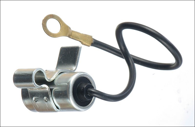
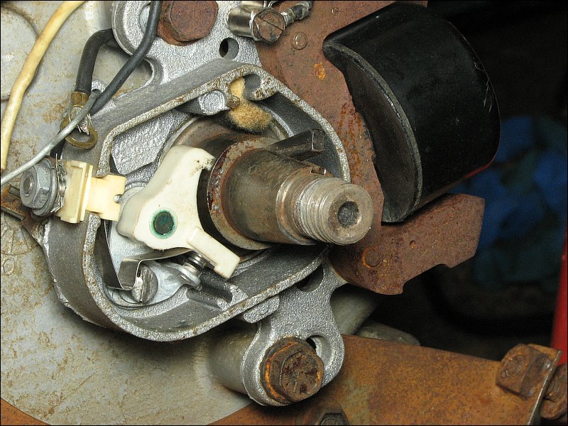 Above, you can see a piece of felt. This is supposed to be oiled (a couple of drops of motor oil is enough). It brushes against the lobe to keep it clean and lubricated to reduce wear of the soft plastic cam follower on the breaker points. In the next photo, the green arrow points to the condenser. The orange arrow points to the ignition coil.
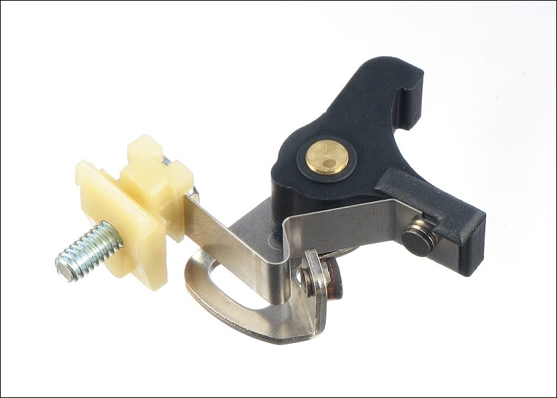
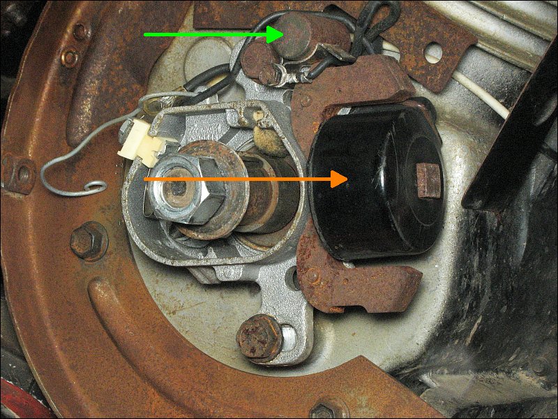 The photos below show what the breaker points and condenser look like. The 'condenser' is simply a high voltage capacitor. These rarely fail but when they do, you will see an increased burning of the breaker point's electrical contacts. If the contacts for the breaker points burn, the breaker points need to be replaced. They can sometimes be cleaned but they typically won't continue to work well if they were badly damaged. If they're just slightly dirty, you can clean them by inserting a piece of cardboard or heavy paper stock between them and working it back and forth. Using a bit of light oil (WD-40 or similar) can help with the cleaning.
 When points are just a bit dirty, you can clean them as suggested above. When they're more seriously pitted or coated, you'll need to use a bit more aggressive abrasive (400 or greater grit sandpaper). Generally this only needs to be done to points that have been in use. The points below were brand new and had some sort of hard coating on them. When they were installed and the engine was checked to see if it was producing a spark, there was absolutely no spark. I removed the wires from the screw terminal on the points and checked for continuity with a multimeter. When the points close, you should essentially read 0 ohms across them. When they open, the meter display should read the same as when the probes are in contact with nothing but air.
 Above, the points were checked with a multimeter. When doing this (unless you know your meter and the components connected to the points VERY well), you should remove all wires from the terminal on the points. This prevents the readings from being skewed by other components. For this system with all wires connected, the reading on the points was about 1 ohm with the points open and about 0.2 ohms with the points closed. Some meters will have trouble showing that small of a difference.
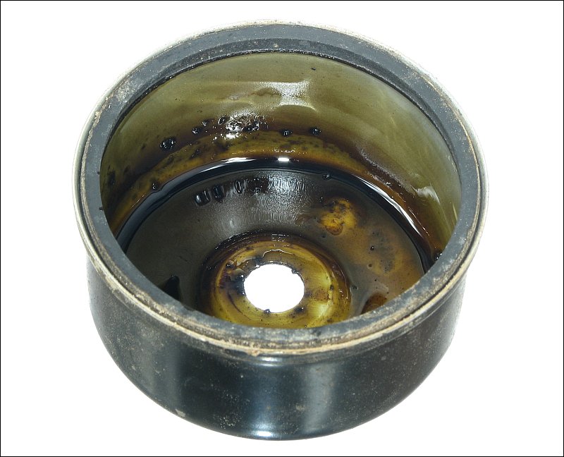
This engine uses a gravity fed, float type carburetor. This one was stored for about 4 years with no preparation. The old fuel was simply left to break down into a nice sludge. It was so bad that the fuel hard hardened in the threads. There was some concern that the retaining nut was going to break off when trying to remove it. If the carburetor would have been expensive to replace if damaged, it would have been soaked in carburetor cleaner to break up some of the varnish before attempting to remove it. Below, you can see the float, the bowl retaining nut and the bowl.
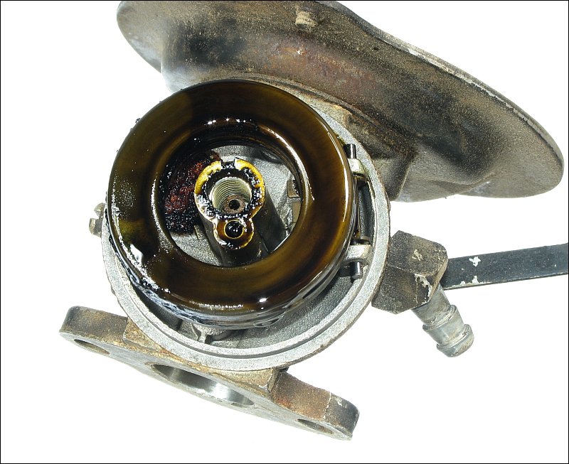
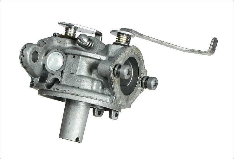
 To clean it out, all removable components were removed from the body of the carburetor. The body and all metal parts were left to soak overnight in Berryman Chem-Dip (part #0996 - available at Wal-Mart for about $20). After about 24 hours, they were checked and most needed a bit more cleaning. A wire brush and a paint brush were used to help remove some of the remaining heavy deposits. The parts that needed additional cleaning were soaked again (for about another 18 hours). At this point, most parts were clean enough. The bottom hole in the bowl retaining nut (that the jet screws into) still required a bit more cleaning because the larger hole had not completely opened up. When you take a carburetor out of the dip, you should immediately blow compressed air through all of the holes that you can find. Since the holes sometimes lead to passages that are aimed directly at your face, you should hold it in a clean rag when doing this. This is what the body of the carburetor looked like after cleaning. The dip removed most of the paint along with all of the varnish (old fuel).
 When cleaning a carburetor like this one, you can sometimes reuse the old parts. This carburetor used all metal to metal surfaces for the jets and the needle valve (the one operated by the float). Where possible, it's better if you buy a carburetor 'kit' for the carburetor that you're rebuilding. When you buy a kit, it will often have a few parts missing (those that you're expected to reuse) and a few extra parts (so that the kit covers several models). It will also have a few parts that are only rarely needed. The gray discs are 'Welch' plugs. These cover various cavities in the carburetor body. These can be difficult to replace without doing additional damage to the carburetor. To remove them, you have to punch through them and pry them out. When punching through, you can sometimes damage the ports in the casting under the plug. It's also possible to damage the perimeter of the hole when prying them out. This can make it difficult to get a good seal when the new plug is installed.
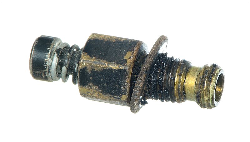
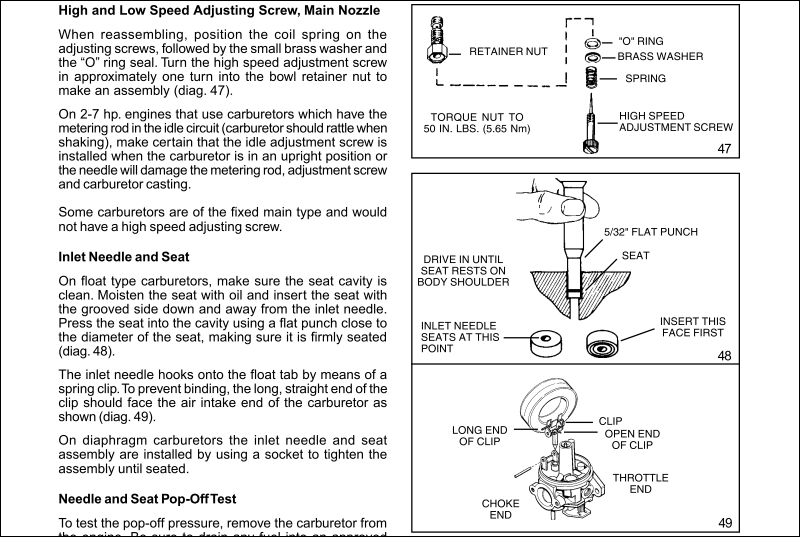
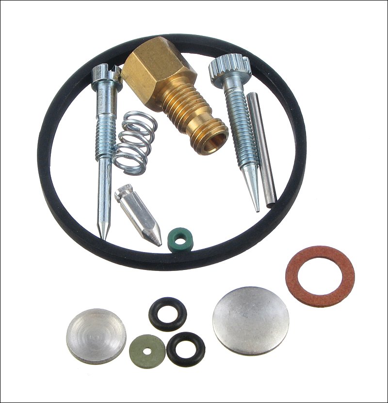 Sometimes a kit will have parts that seem identical but have very slight differences. In the kit above, the green seal was included to be used as the seat for the needle valve. Originally, the carburetor had a metal to metal valve. To use the rubber seat, you would need a shorter needle than the one that was included. Using the included (or the original) needle wouldn't allow the float to reach the correct (level) position (no matter how far it was bent). The new needle was used without the rubber seat (as the old needle was) and it didn't work reliably. Sometimes the valve would seal and sometimes it would allow an unlimited flow into the bowl which caused fuel to spill out of the carburetor. The new needle had a very slightly blunted tip where the older needle had a sharper point. Another problem with this kit was the main jet. The jets must be able to hit their seats so that they can seal completely. They won't be used in the closed position but they have to be able to get there because they may need to operate very close to completely closed. The kit's components looked identical to the original parts but they were not. The main jet would not screw into the bowl nut far enough to seat. You could screw the jet in completely then screw in the bowl nut and the nut would bottom out against the carburetor body. The problem would have been even worse (the jet's needle would have been held even further from its seat) if the bowl and the washer would have been in place (as they would have been when the carburetor was fully assembled). This was obviously not right because the needle of the jet should have contacted the seat before the nut bottomed out. With the original jet screwed completely into the original bowl nut, the jet would bottom out about 1/16th of an inch before the nut bottomed out. If you've never rebuilt a carburetor of the type you are working on, it's easy to forget where every washer and seal goes. If you look up the service manual for the engine or carburetor, there will be exploded diagrams that show the placement and order of the various components. For example, on the main jet, you have to install the tension spring, the brass washer and the o-ring in that order. Below is an example of the information that is included in the 3-11hp L-head technician's manual published by Tecumseh.
|
|
|
|