 |
| Email Home Page |
|
| Email Home Page |
|
|
|
Rules:
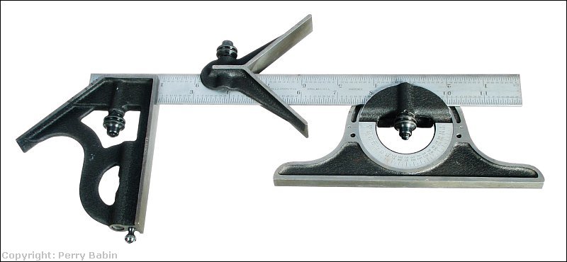
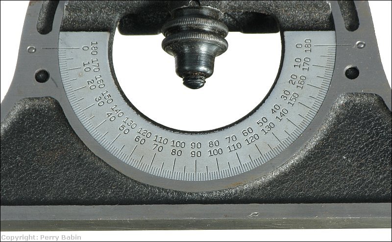
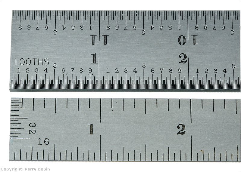 The following is a Starrett combination set that includes a 12" rule, a 45/90 square, a center head and a protractor head. The 45/90 head is a standard combination square. The centering head allows you to make marks precisely across the diameter of a round object or from the corner of a square object. The protractor head can be used to either measure angles or can be set to a precise angle to allow you to transfer that angle to the workpiece.
Tape Measures:
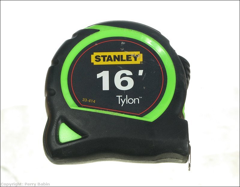 When buying a tape measure, you'll generally have a choice for the width of the blade. For something where you will not need the blade to be self-supporting over long distances (out to 5 or 6 feet), you can choose one with a fairly narrow blade. If you need it to stay rigid and self-supporting for long distances, you'll want a wider blade. It may seem like that would be no reason to choose one with a narrower blade but the tape measures with the wider blades are heavier, more bulky and more expensive. Most people have several so they can choose the one best suited for the task at hand.
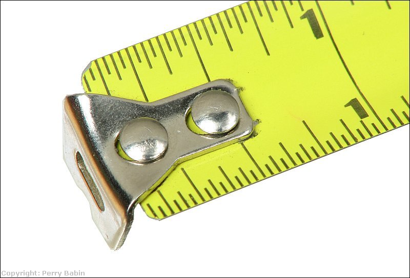
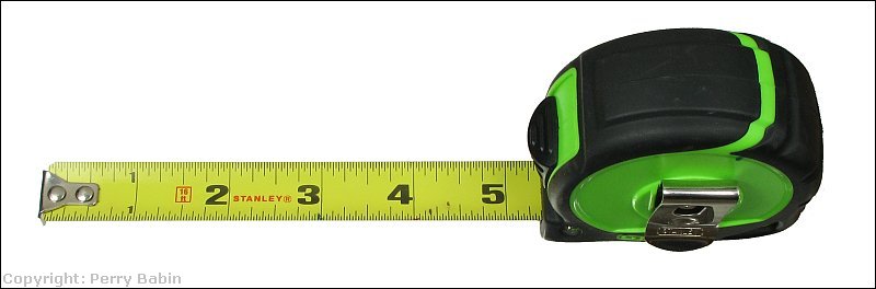 Most tape measures have locking mechanism to keep the blade extended. These can be in various places (front, bottom...). You should choose one that's best suited for you. Typically, the tape measures with the lock directly above the blade (like the one above) are the easiest to use. The hook on the end of a tape measure is connected in a way that allows it to move in-out the thickness of the hook. If the hook were firmly attached, you would only be able to get accurate measurements when the hook was outside the edge of the item being measured/marked.
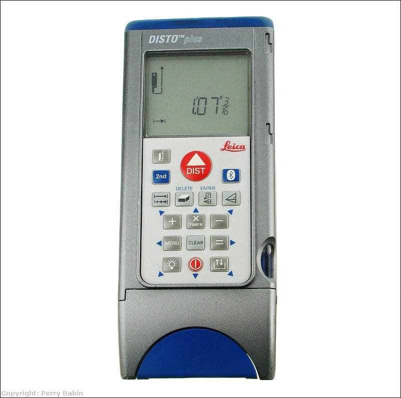
Laser Measuring Devices:
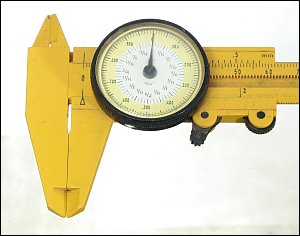
Calipers:
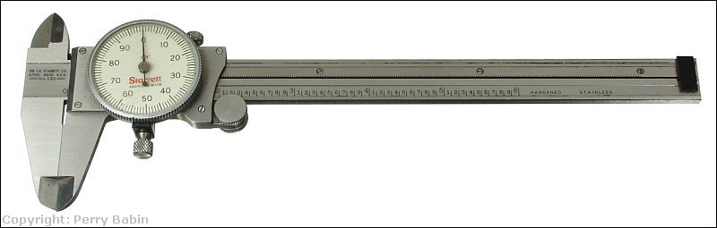 When you use a dial caliper for critical measurements, you need to 'zero' it. This means closing the caliper and confirming that the needle is perfectly aligned with the 0 on the dial. If it is not, you need to open the caliper and wipe each of the jaws to ensure that nothing is between the jaws preventing them from closing completely. If it doesn't return to '0' properly after cleaning, you can turn the dial to align the dial to the needle. On the caliper above, there are two knurled knobs/screws (one on top and one on bottom). The one on top locks it to prevent the sliding jaw from moving on the beam/bar. The one on bottom locks the dial/bezel to prevent it from turning after calibration. If/when you need to zero the caliper, you will need to loosen the bottom knob slightly so that the bezel will turn freely. You will tighten it again after calibration, double-checking to confirm that nothing has moved when you tightened the screw. Below, you can see the face of the dial caliper. If you're viewing this site in the order of the directory, you already know how to read these. It was covered on the Basic Metalworking page.
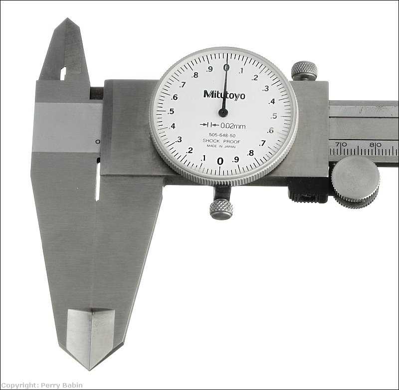
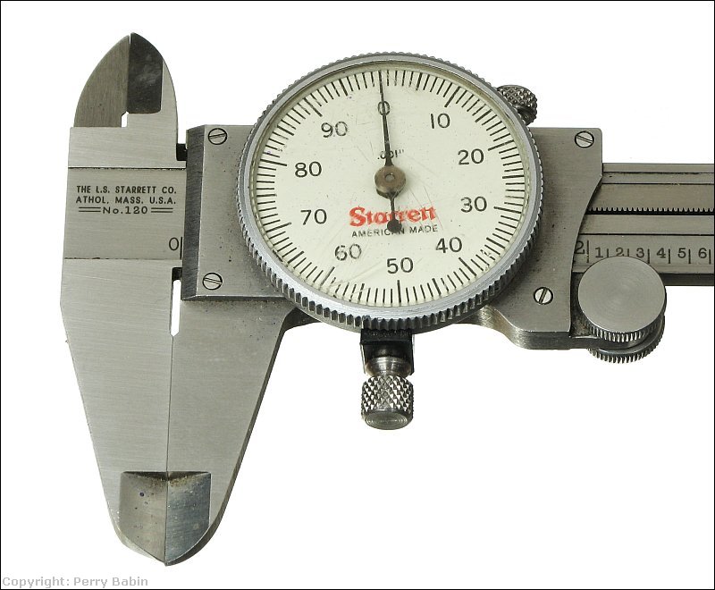 Dial calipers are also available that read in mm. For most dial calipers, the smallest increments on the dial are 0.001". Here, they are 0.02mm.
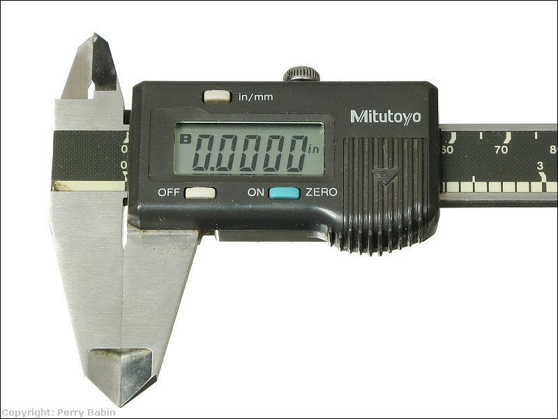
 This is a 'digital' caliper. Mitutoyo is also a professional quality brand. This caliper has a digital display instead of a dial but the function is generally the same. Although I still prefer to work with dial calipers, this one has a few nice features. It allows you to switch between metric and imperial readings. It also allows you to 'zero' it at any point. If you had two items and you needed to know the difference in the two, you could measure one, zero the caliper then measure the other. One advantage of dial calipers over these is that... the batteries will never die on a dial caliper. If you have a digital caliper, be sure to turn it off (not all have an auto-off feature) and make sure that you have spare batteries. In some instances, the on/off buttons can be depressed by the foam packing and switch it on in its case. For those calipers, you will need to remove the batteries when the caliper is stored.
Dial Indicators:
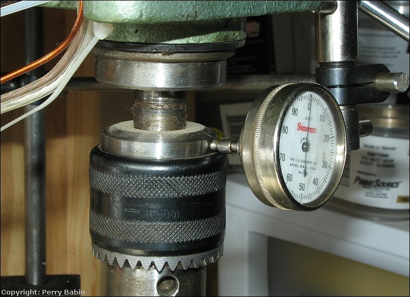
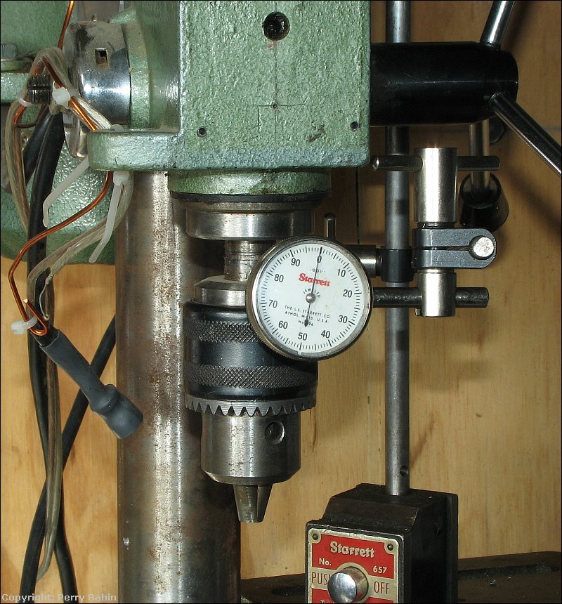 Above, you can see that the dial indicator is mounted with bars and clamps which are held down with a magnetic clamp. The jig must be fairly rigid so that the indicator doesn't move when the component being tested pushes back on the indicators contact point and spring-loaded rack. The image below shows how it makes contact on the spindle of the drill press. You must be careful when performing tests like this. When I initially set it up to take the photos, I had it set in the outside collar of the chuck. The friend that loaned me this setup told me that that wasn't the right place to set it and it should be on the rigid part of the chuck.
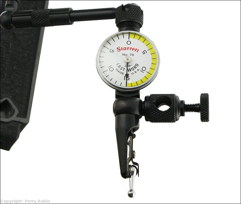
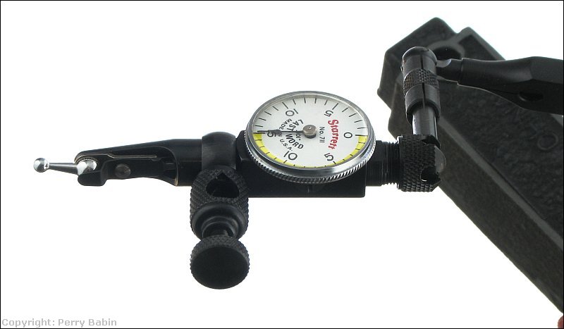
 The dial indicator above works by having it's rack moved in and out. There is another type as well. The one below is a lever type dial indicator. On this one, moving the tip of the lever moves the needle. This is a 'last word' dial indicator (made by Starrett). There are at least two versions of the last word indicators. This one has 1/1,000" increments on the dial. The other has 1/10,000 increments.
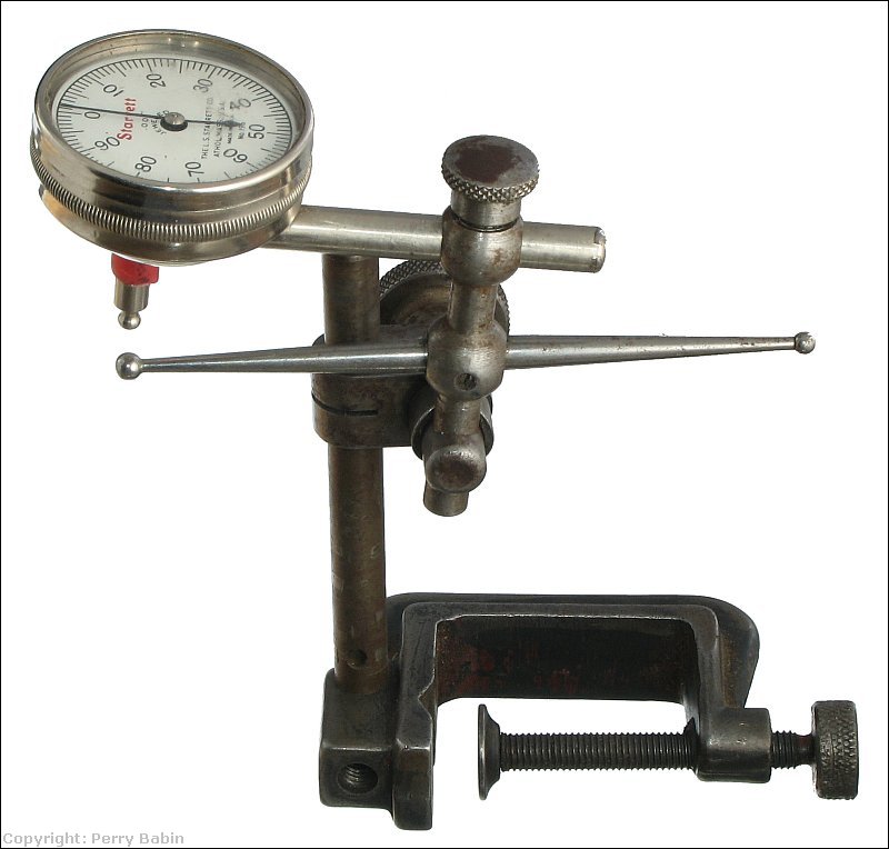
 The next image shows a standard dial indicator with an adapter that allows the dial indicator to be used to check internal bores or to allow you to get the probe on a shaft or coupling where you can't get the dial indicator on it directly.
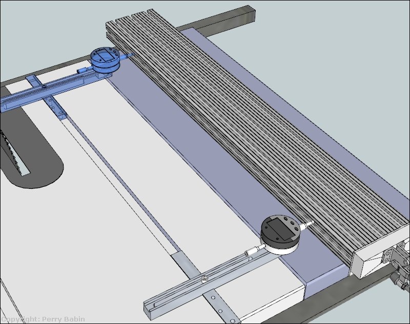
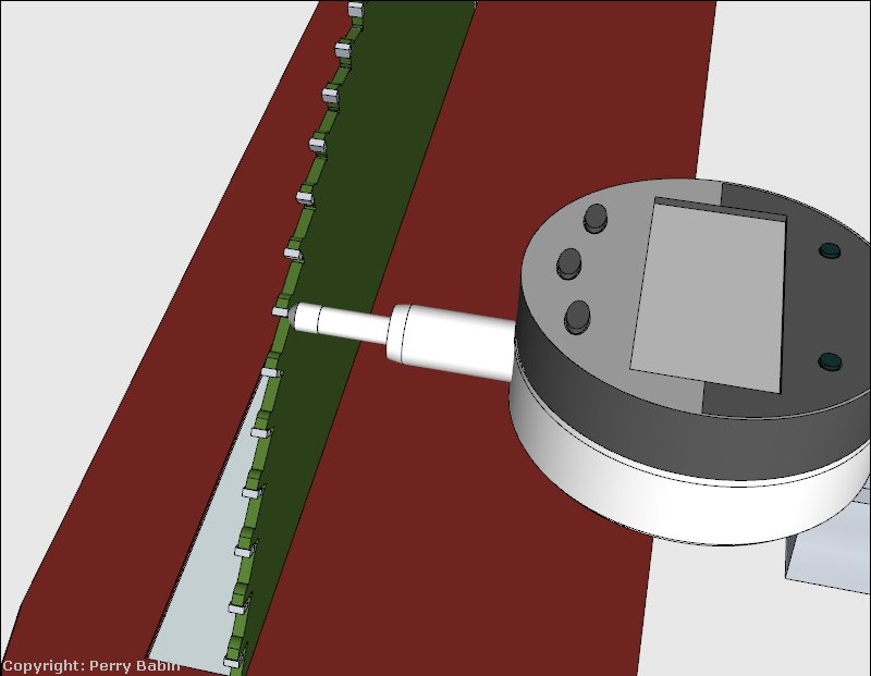
 The following shows one application for a dial indicator. This dial indicator has a base that's designed to fit tightly in the slots in a table saw. You use the dial indicator to confirm that the fence is perfectly in line with the slots in the table. If they are not, they cans cause accuracy problems or can can cause the blade to bind on the material being cut. You set the dial indicator on one end of the fence and zero it. Then you move it to the other end and see how much difference there is in the two readings. You want the fence either parallel to the slots or to slightly open up (about 5 thousandths of an inch away from the slot on the far end of the fence).
 You can also turn it around and check to see if the blade is in alignment with the slot. Most saws need at least a small adjustment. In some instances, there is no adjustment for the motor/blade and you have to drill out the mounting holes to be able to nudge the mounting assembly into alignment. When you do this, you will want to touch the dial indicator to the side of one of the teeth. Then, when you move the indicator to the other side of the blade, you rotate the blade and use the same exact tooth. You can also use an alignment plate. The plate is a thick piece of precision finished steel that you install in place of the blade. This is really only required for someone making quality furniture. USing the blade is good for most of us.
Micrometers:
 There are two ways to have a wide range of micrometer capacities. You can have 6 different micrometers or you can have one frame with interchangeable anvils. The image below is a set with one large frame with interchangeable anvils. This is generally less expensive than 6 complete micrometers but always having to work with the large frame isn't as convenient as having all of the individual micrometers.
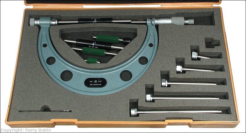 In the image above, there are several lengths of metal. These are called 'standards'. They're produced to have a very accurate length and are used to calibrate measuring devices like micrometers. Below is a 4" 'standard'.
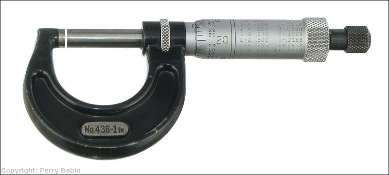
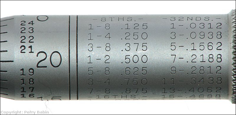
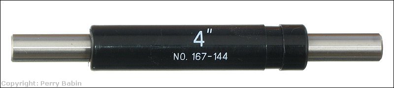 The next image shows the markings on the thimble of a micrometer. You use these for fine readings. You use the marks on the body of the micrometer to read the larger increments. For every full turn of the thimble, the spindle moves 0.025" (25 thousandths of an inch). The other marks are simply a conversion table for commonly used fractional increments. Not all micrometers have these.
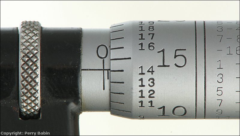
 Below, you can see that there is one exposed minor increment. This means that the micrometer is open at least 0.025". Of you look at the markings on the spindle, with reference to the line on the micrometer, you can see that the thimble is just a bit over 14 thousandths into its second full rotation. If you add 14 to 25, you get 39 thousandths of an inch (actually just a bit more). This micrometer was measuring a 1.00mm feeler gauge. If you convert 1mm to inches, you get 0.0394". This micrometer is reading about 0.0391 so it's pretty close. It's hard to say which it off but it's likely the feeler gauge.
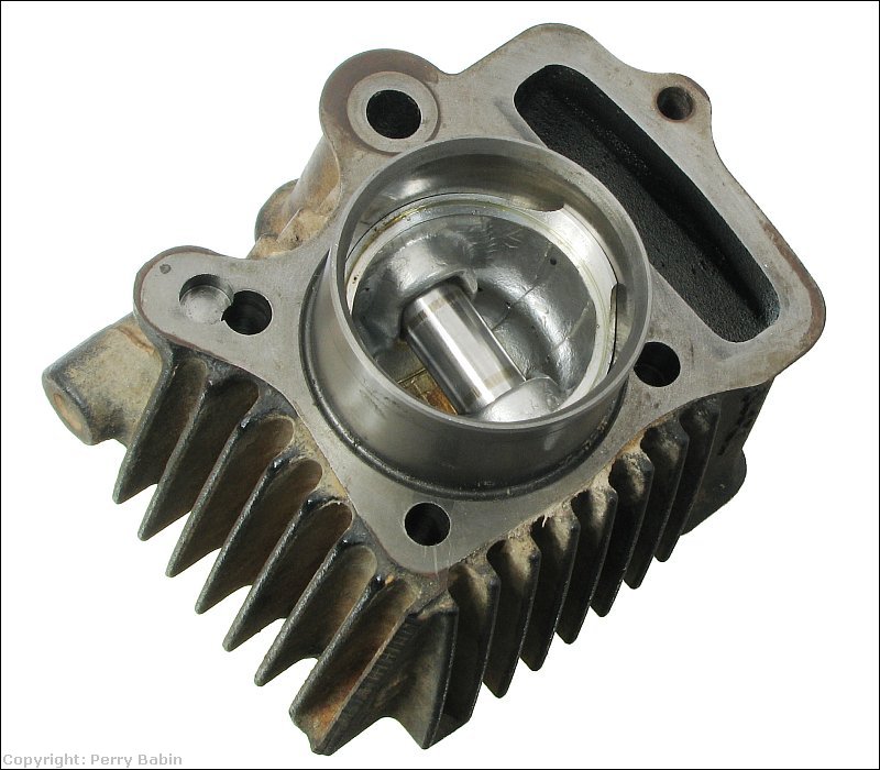
 Micrometers are often used by machinist when they need the greatest accuracy. When building engines, you will have a list of specifications for virtually every internal part. When assembling the engine, you would need to check all critical parts to confirm that all parts meet spec. The term 'blueprinting' as it applies to engine building refers to building an engine that's as close to the design specs as possible. One thing that you would check when building or rebuilding an engine is the diameter and bore of the components like the wrist pins and the crankshaft journal as well as the bores in both ends of the connecting rod. The photo below shows the bottom of a cylinder head and piston for a 70CC Honda motorcycle. The cylindrical part that goes across the piston is the wrist pin. With the wrist pin out of the cylinder, you would check its diameter at several points and all around to confirm that it meets spec. It measured just over 511 thousandths of an inch. The specs say that it should be 13.0mm. If you convert .5113 to millimeters, you get 12.987mm which is close enough for an engine like this.
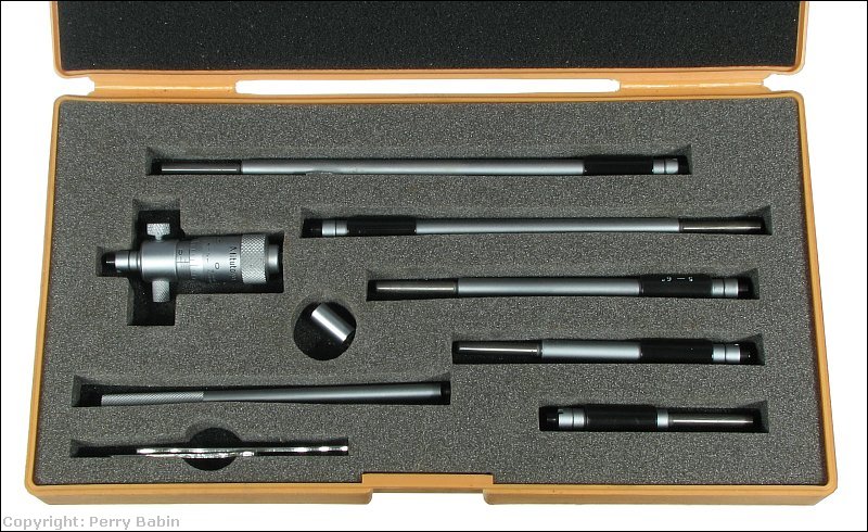
 Previously, you saw an 'outside' micrometer. The one below is an 'inside' micrometer. These are used to check the internal dimensions of bores or the distance between two points. Again, this one comes with several accessories that allow it to be used for several ranges. You would use something like this to check the bore on the cylinder of an engine. You'd set it to the diameter that the cylinder should read and then insert it into the bore of the cylinder to see if the cylinder matches its specifications. If it were a bit loose when set to the manufacturer's specs, you'd adjust it to determine what the actual bore is. Then you'd compare the actual measurements to the tolerances set by the manufacturer to determine what needs to be done to repair the engine. Sometimes, if it's too large, you'll bore it to the next larger size and use over-sized rings and pistons. For really worn cylinders, you may bore it and install a sleeve in the bore.
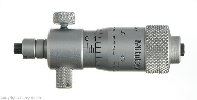
 Looking at the setting on the micrometer below, you can see that it's 2 ticks beyond the 0.100" mark. That means that it's set to 2.102". The micrometer and the shortest extension are 2" minimum. The reading on the body of the micrometer is 0.102".
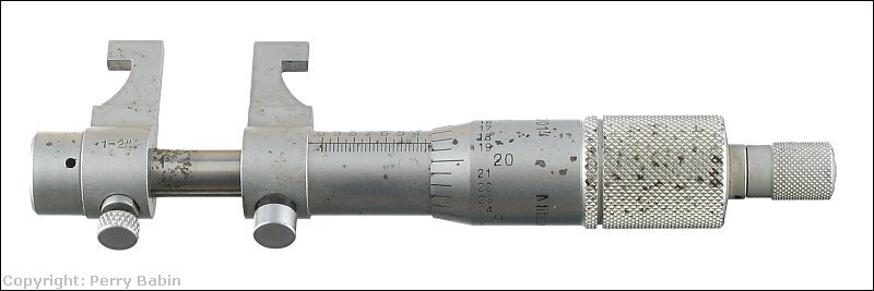
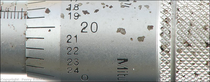
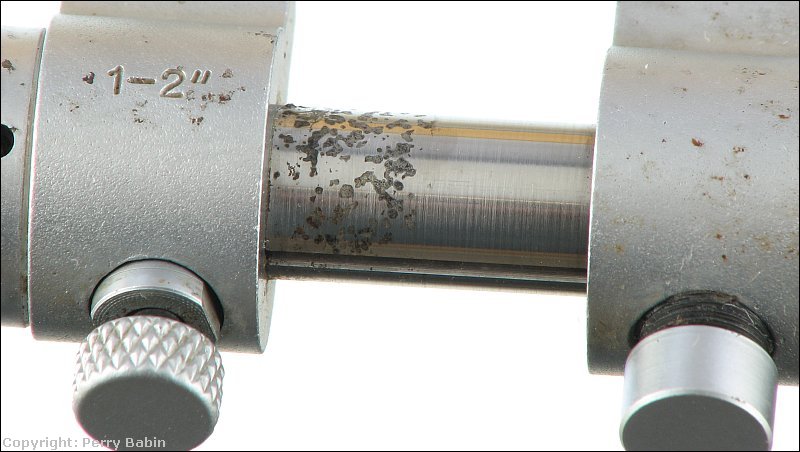
 This is another inside micrometer but what you should see here is the damage created by the protective foam as it deteriorated. It stuck to and attacked the metal. Most of the black spots are actually pits in the metal. If you have sensitive tools stored in containers that use foam, you should check them to ensure that this isn't happening to your tools.
Combination/Venier Calipers:
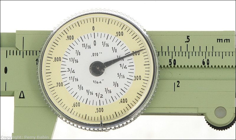
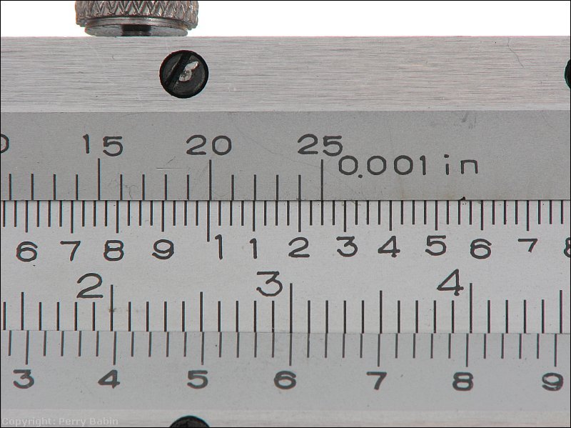
 This caliper also give a reading on millimeters but the markings are on the body of the caliper instead of on the dial. To read millimeters, you have to look at two sets of markings. The markings to the left of the dial are whole millimeters. The markings on the right give you the 1/10th millimeter readings. If you look carefully at the alignment of the top 1/10th millimeter marks with the bottom marks, you will see that none line up in the first photo. The first mark is slightly to the left of the line under it and the last mark slightly to the right of the line under it. This and the fact that the 5mm mark appears to perfectly in line with the mark under it tell you that the caliper is reading exactly 5mm.
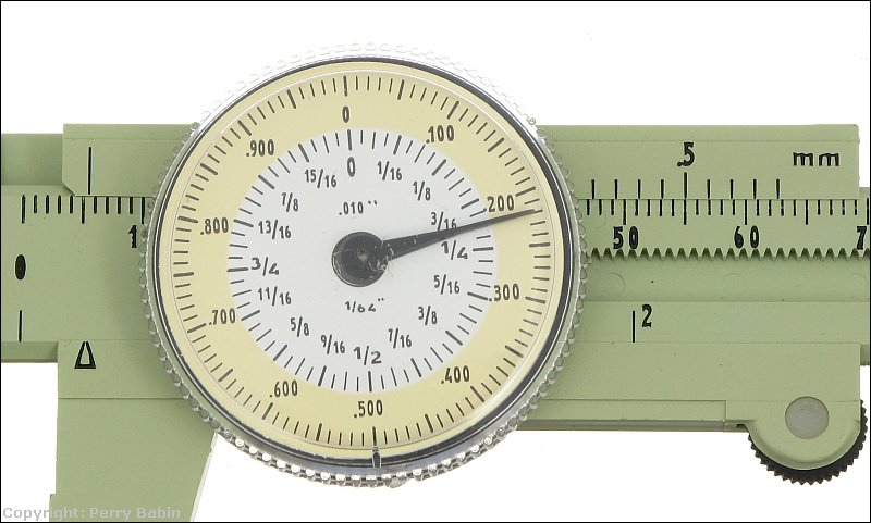
 This photo shows you the caliper reading 5.5mm. You can see that the left mark is half-way between 5 and 6. On the right, you can see that the only top mark that's perfectly aligned with the mark under it is the 0.5mm mark. If the caliper was opened 0.1mm, you would see that the mark to the right of the 0.5mm mark would be in perfect alignment with the line under it.
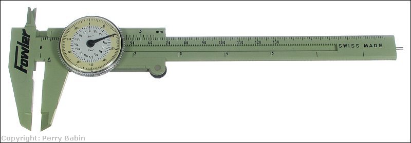
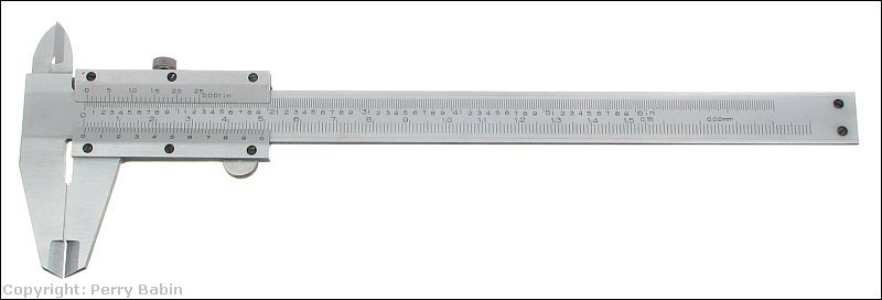
A side note... The next caliper is a vernier caliper. It can measure down to 1/1000th of an inch (if you have very good eyesight). The vernier scale works like the caliper above but the marks allow it to read more accurately. As with the micrometer, the scale is broken down in 25/1000th increments on the beam. With the micrometer, you had to turn it 1 complete turn to move the spindle in or out 25 thousandths of an inch. Here, the distance between the minor marks on the beam is 25/1000ths.
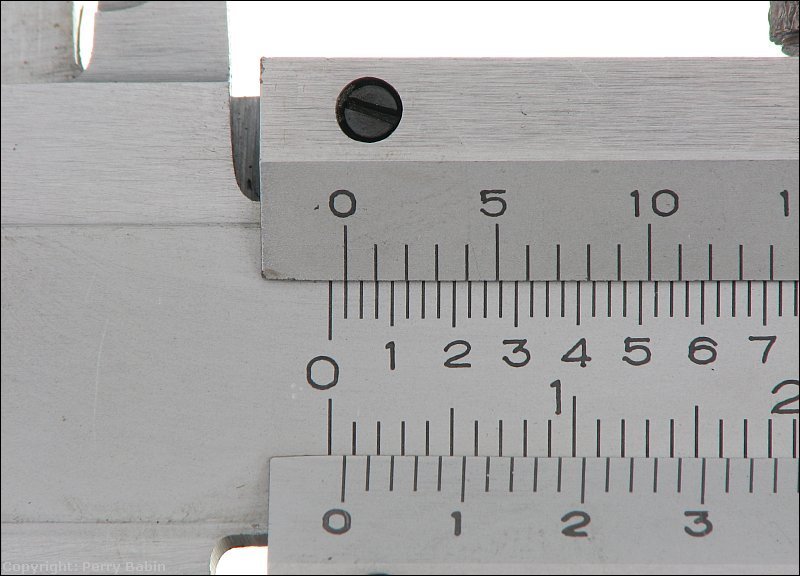
 When you look at the marks for inches (top marks here are inch, the bottom are mm), you can see that there are 4 divisions between the 1/10th inch marks. The marks you look at for proper alignment with the marks below them have 25 points here. I tried to set it to precisely 0.025" but it was not easy to do. If you look at the alignment of the marks, you can see that it's difficult to tell if the 24 or the 25 mark is in alignment with the mark below it. It's likely that this is closer to 0.024 than 0.025.
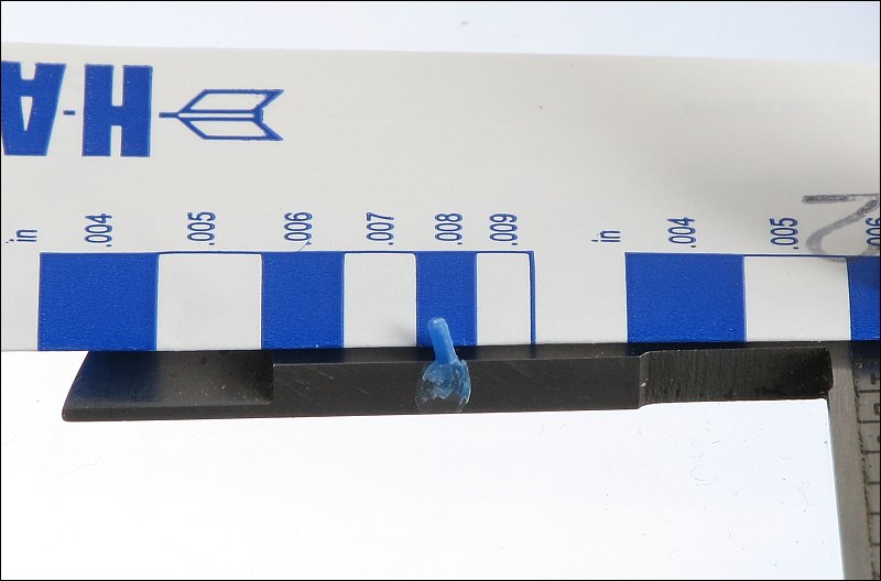
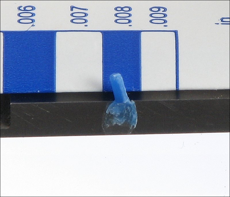
Plastigage:
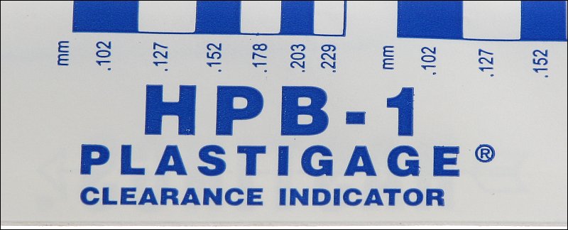 I didn't have a connecting rod and crank handy so I squeezed a length of Plastigage between the jaws of a dial caliper down to about 0.008". You can see how it spread out about the same amount that's indicated by the 0.008" reference on the sleeve. Some of it pulled off but it left enough residue to see how wide is was when compressed.
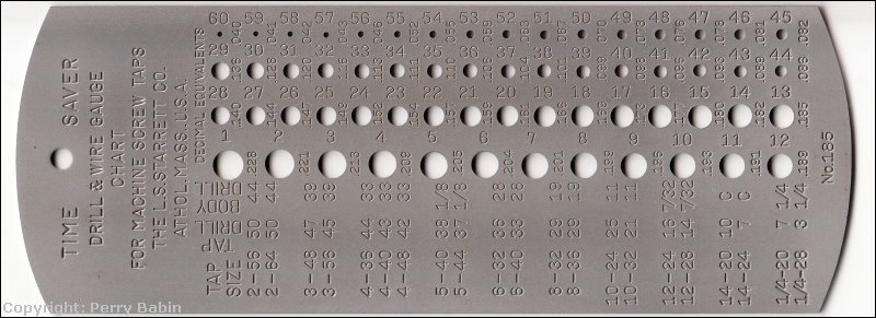
Drill Gauges:
|
|
|
|
 There are all types of measuring devices. Some are very accurate and some, not so accurate. This doesn't mean that the not-so-accurate ones aren't of any use, for example, when measuring long distances, you typically don't need accuracy down to the foot or even to the inch. Using a measuring wheel may only be accurate to ±6 inches but that's easily good enough when measuring a large area to estimate the amount of seed or fertilizer you'll need. In other instances, like when you're building an engine, you would need accuracy down to the thousandths of an inch. This page will cover many of the types of measuring devices that you may need for various tasks.