 |
| Email Home Page |
|
| Email Home Page |
|
|
|
Part 1
Google's Sketchup is a 3D graphics application that's incredibly powerful, especially if you consider that it's absolutely free. The free version doesn't have a lot of the features of the full 'PRO' version but it has enough features to do most of what I've needed to do with it. In the 'Alternatives to MS Paint' page of this site, you were introduced to the program in a very general way. On this page, you'll see what it takes produce simple objects (which, when combined, can be used to produce more complex items). To make it easier to follow along, go download the latest version of Sketchup and install it now. In the following image, you can see the Sketchup interface. It's very similar to other graphics software that you've likely used with a few exceptions. The 'axes' (red, blue and green) are displayed. The point where they intersect is the center of the stage. The solid lines go up, back and to the right. The dashed lines go below the stage, to the left and towards the camera (the viewing position). You will need these to keep yourself oriented since the objects can be viewed from any angle.
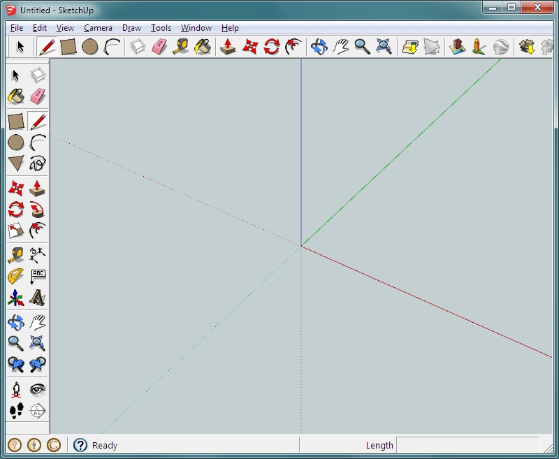
Viewing Images:
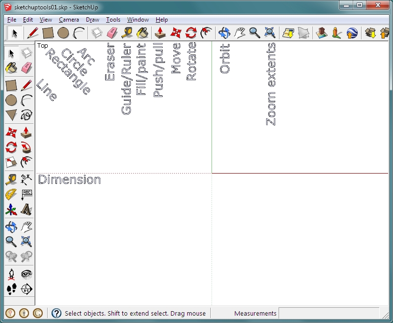
 Below, you can see the most commonly used tools (for me). Try a few of them. You will have to use the orbit tool to move around your 3D models. Many of the other tools are used to create the basic shapes needed to create your model.
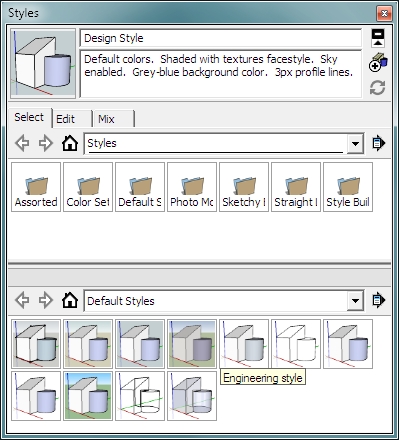
 There are several viewing styles available. The best general purpose styles (in my opinion) are the engineering and the x-ray. To change from solid to x-ray mode, from the toolbar at the top of the page, click WINDOW >> STYLES >> choose x-ray (last in the list). If switching modes causes all of the guide lines to be displayed (and you intentionally had them turned off), click VIEW >> and de-select GUIDES. Sometimes you have to orbit or zoom a bit to make the changes take affect.
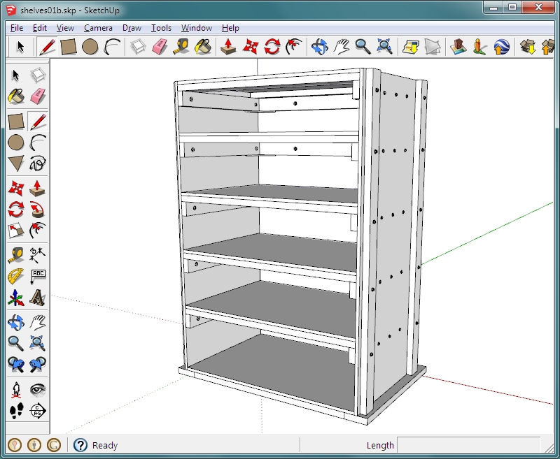
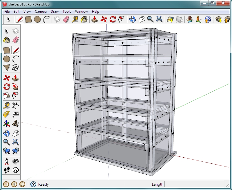
 THIS is the file of the heavy duty shelving unit that you saw (or should have seen) on the MS Paint Alternatives page. The two images below show it first in 'engineering' style. The second is in x-ray style. If you open this file and the shelving unit isn't centered in the frame, use the 'zoom extents' button. That will show the entire object.
Camera Angles:
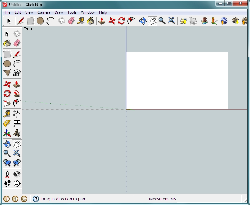
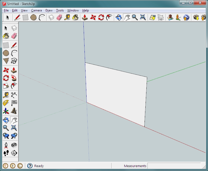
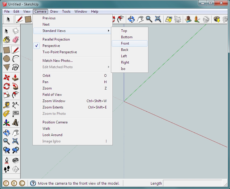 The following is a rectangle drawn with the camera angle set to 'front' (notice the text in the upper-left corner of the window). The second photo is the same object with the camera angle set to 'iso'.
Note:
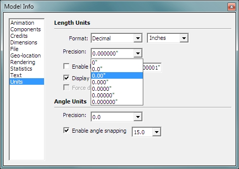
Building: Since tolerance has come up in the discussion, you should know that the precision of hand drawn components can be set. For this, you go to WINDOW >> MODEL INFO and select UNITS in the menu. Initially, the units will be fractional (1/2, 5/8). For those who prefer the decimal format, you can set it to that. You can also set the precision. The precision makes the dimensions snap to the increment chosen. If it's set to 0", it will snap to full inch increments. If it's set to 0.00", it will snap to 1/100" increments (0.05, 0.06, 0.07...). You'll have to choose the precision based on what you're drawing. A piece of metal to be machined on a mill will need a higher precision than a wooden planter.
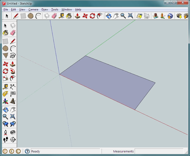
 The most basic tools are the ones that create simple rectangles or circles. To make a rectangle, select the rectangle tool. Click and release near the point where all of the axes intersect and move the mouse until you see a rectangle with the type of length/width ratio that you want (long/skinny or short/fat). Look at the bottom right corner. You will see the measurements of the rectangle that you drew. Notice which is greater (dimensions before the comma or the dimensions after the comma), that's the long dimension of the rectangle. Enter the dimensions that you want, separated by a comma and press enter. The rectangle will now be the size you entered. If it doesn't fit your screen well, use the mouse wheel to zoom to the desired size. In the previous graphic, there was a tool named 'zoom extents'. Clicking that button will make the object as large as possible (with just a bit of space all around). It was suggested that you start drawing at the intersection of the axes. This is not required but if you're starting out with the bottom of whatever you're drawing, it's good to draw it there. This places it, basically, at ground level. If you draw objects starting just anywhere, you will often inadvertently draw them very high or very low on the stage. This can make them difficult to work with or to move into position. Remember, this is a 3D program. You're not drawing on a flat piece of paper. You're creating objects in a 3-dimensional space. At this point, the rectangle is a plane (has no thickness). If you were drawing a wall or a piece of plywood that was to be a shelf (like those in the shelving unit used previously as an example), a flat plane wouldn't accurately represent the plywood. To make it thicker, select the push/pull tool. Click the face of the rectangle and drag the cursor up. You can do this freehand but it's generally best to enter the required thickness as you did for the other dimensions of the rectangle.
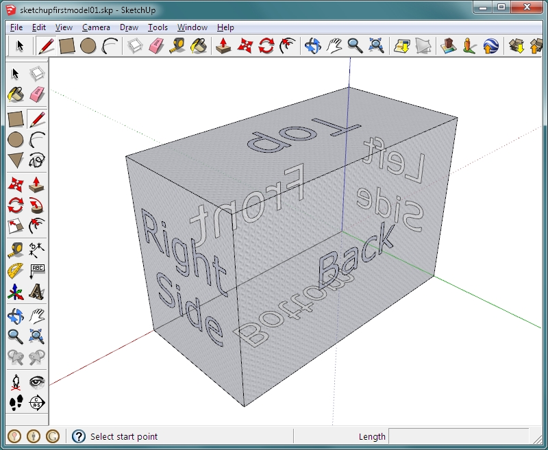
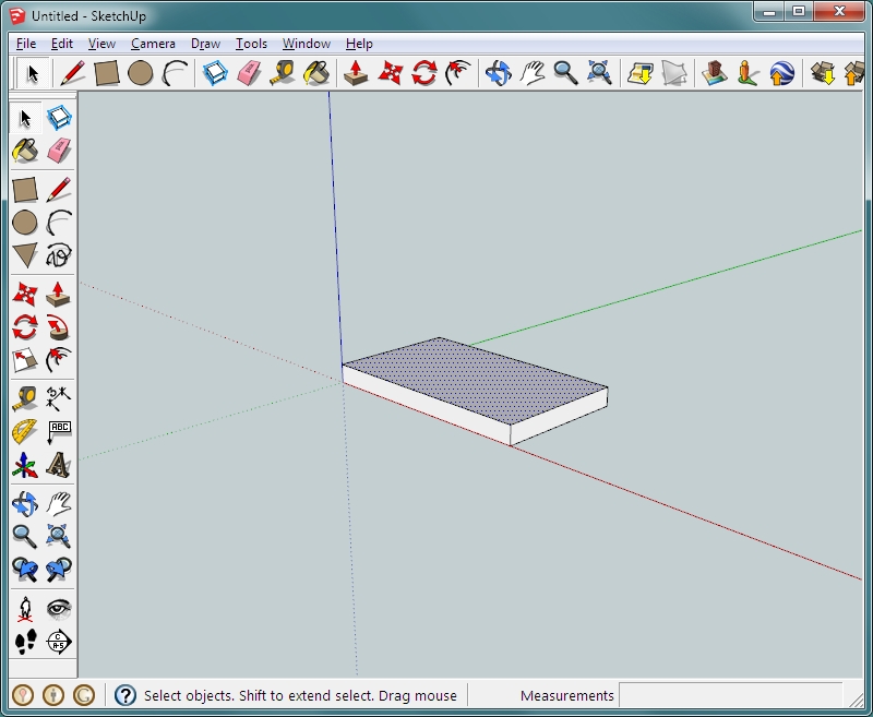
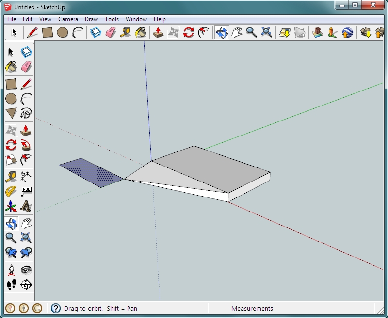
 Selecting an object is done by using the arrow/select tool (upper left-hand corner of the tool pallette). When working with an object that's a flat plane, there are two ways to select and they work a bit differently for various tools. For example, if you draw a rectangle, it has a border and a center-fill. If you click the center once, you select the fill without the border. If you click DELETE, you will delete the fill but leave the border. If you, however, use the 'move' tool, it will move the fill and the border together, even though only the fill is highlighted. When working with 3-D objects (those with height, width and depth), selecting it is a bit different. You can (as always), click outside the object and drag a box around it. Anything in the box you drag will be selected. If you want to select only one face (to change it's color or texture or to delete it), you click once. Clicking twice will select the border for the face as well. If you click three times, the entire object will be selected. In the image below, only the top has been selected. If a double-click were used, the top border would have turned blue to indicate that it was selected as well.
 At this point, it's best to group the object if you're going to draw other objects that may touch or overlap the object that you just created. That will prevent them from combining. Any lines or objects that are not an individual component or group will combine if they make contact in the drawing. In the example below, a rectangle was drawn with one corner touching the rectangular box. When the flat rectangle was moved, it dragged the bottom corner of the box with it. If you accidentally draw something like this and want to correct it, use the undo function (ctrl-z is the easiest; ctrl-y is redo).
 If you will need multiple identical objects, you should build one and make it a component or a group. If you copy a group multiple times and edit one of the duplicates, only that particular grouped object will be modified. If you modify one of a number of copied 'components', ALL of the components get the modifications. To make an object a component or group, you go to EDIT >> and select either from the menu. You can also right-click and choose either from the dialog box. When you need to move an object, it has to be selected before it can be moved. In most graphics software, you can click and drag an object with the same tool. You cannot do that here. If you have an object highlighted and click and drag another object, the highlighted object will move, even though the cursor is on a different object. Another useful ability is that to make openings or holes in an object. If you will have multiple through-holes in an object, it's generally easier to make those holes while the object is still a flat plane. Make the holes by drawing other objects on top of the object. Then select and delete the insides of the objects that you drew on the larger object. After you get all of the openings cut, use the push/pull tool as you did previously. The openings in the flat object will become through holes. To make holes that are not through-holes, you make them after the object has been pushed/pulled. Again, you will draw on top of the object where you want the hole. Then you will use the push/pull tool to move the face of that object inward. Again, you can drag and release or click and enter the depth value
Guide Lines: This is the end of part 1 of the Sketchup tutorial. Click HERE to go to part 2 (10b in the directory).
|
|
|
|